To promptly assess regional earthquake damage, several seismic alarm systems have been created around the world. This study in the journal Buildings compares the suggested method to refined finite element model analysis and simplified model analysis and recommends a method for the rapid prediction of seismic damage to urban buildings utilizing low-LOD information.
Study: A Brief Method for Rapid Seismic Damage Prediction of Buildings Based on Structural Strength. Image Credit: schlyx/Shutterstock.com
Earthquake warning systems use fragility curves to assess structural damage quickly after an earthquake occurs. Such fragility curves are created using a small database and a set of preset categories that take into account the change of a few attributes.
This study compares the suggested method to refined finite element model analysis and simplified model analysis and recommends a method for the rapid prediction of seismic damage to urban buildings utilizing low-LOD information.
Methodology
Empirical fragility analysis has been utilized for residential buildings in studies aimed at forecasting seismic damage to urban structures using physics-based methodologies. The capacity spectrum method (CSM) is a computationally efficient method that uses pushover curves to analyze building attributes.
Torsion effects impact the seismic responses of buildings built to have abnormalities, and typical assessment methodologies may not perform well on such structures. Seismic damage indices (DIs) are another extensively used deterministic technique.
DIs can affect a structural component, a structural member, a section of the structure, or the complete structure. It is frequently used to make preliminary damage assessments.
For a few construction categories, simplified stick models of a similar type have been constructed separately, and their correctness is dependent on parameter calibration. Because there is a scarcity of data on urban structures, some of the parameters of the simplified models are established by statistical analysis, which introduces uncertainty into the models.
To analyze uncertainty in structural properties, sensitivity analysis methods such as the Monte Carlo method and the first-order second-moment method are frequently utilized. When the total number of regional buildings is significant, parameter uncertainty has a minor impact on the analysis outcomes.
However, in the case of individual building analyses, the uncertainty cannot be overlooked.
Soft computing techniques have been used in a variety of research to develop quick methods of seismic vulnerability assessment. Based on field observation by professionals, these methods use probabilistic methodologies, meta-heuristics, and artificial intelligence (AI) methods to create correlations between specified preliminary parameters and damage states.
Soft computing techniques applied to quick seismic risk assessment could eliminate biased field judgment by poorly qualified engineers and tackle the difficulties of the inherent uncertainty in the real world.
Data-driven vulnerability correlations of buildings from one area may not work well on buildings from another area due to differences in design and materials used in building construction.
HAZUS recommends overstrength factors for buildings, and the values of overstrength factors for Chinese buildings were determined using statistical analysis in the structural study of Chinese structures.
The seismic resistance index of structures is determined using structural overstrength in a suggested approach for regional seismic structural damage prediction. The result of the design strength level and the overstrength factor is the seismic resistance index.
The design-strength-based strategy is depicted in Figure 1 as a flowchart. The spectral acceleration Sa can be used to express the earthquake load for a particular seismic ground motion (T1).
With a few parameters and a statistical procedure, the natural period T1 can be calculated (e.g., number of stories, structure type, basic building plan sizes, and building height). The seismic design code employed in the building’s design can be decided by the building’s construction time and seismic zone.
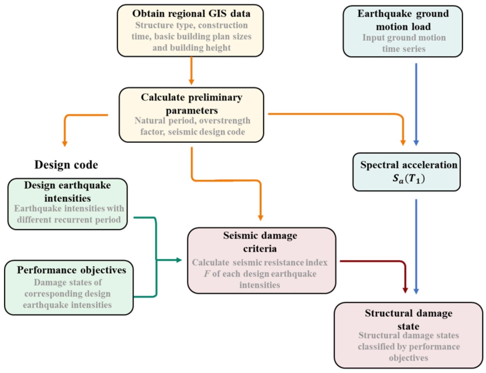
Figure 1. Flowchart of the design-strength-based seismic damage prediction method. Image Credit: Zhang, et al., 2022
The earthquake intensities are classified as common earthquakes, moderate earthquakes, rare earthquakes, and extremely rare earthquakes in the Chinese Code for Seismic Design of Buildings and the Seismic Ground Motion Parameter Zonation Map of China.
The earthquake intensities related to recurrence periods and performance objectives are provided in Table 1.
Table 1. Design earthquake intensities and performance objectives in Chinese codes. Source: Zhang, et al., 2022
| Earthquake Intensity |
Recurrence Period (Years) |
Probability of Exceedance |
Performance Objective |
| Frequent earthquake |
50 |
63% in 50 years |
Operational |
| Moderate earthquake |
475 |
10% in 50 years |
Damage repairable |
| Rare earthquake |
2475 |
2–3% in 50 years |
Collapse prevention |
| Extremely rare earthquake |
10,000 |
0.01% per year |
Probable collapse |
The seismic resistance indices of four earthquake intensity levels, as indicated in Table 2, are the criterion for structural damage state utilizing the design-based method.
Table 2. The design-strength-based method’s structural damage criteria. Source: Zhang, et al., 2022
| Damage States |
Range of Seismic Resistance Index |
| No damage |
[0, Ωy×Sa(T1) (frequent earthquake)] |
| Slight/minor damage |
Ωy×[Sa(T1) (frequent earthquake), Sa(T1) (moderate earthquake)] |
| Moderate damage |
Ωy×[Sa(T1)(moderate earthquake), Sa(T1) (rare earthquake)] |
| Extensive damage |
Ωy×[Sa(T1) (rare earthquake), Sa(T1) (extremely rare earthquake)] |
| Complete damage |
Ωy×[Sa(T1) (extremely rare earthquake), +∞ ] |
For the structural damage states in the current study, the earthquake design intensities and performance objectives in the Chinese codes were used. The concept of this method can also be used in structures built for other seismic design codes.’
Results
The seismic response of the two methods is compared to that of the proposed method, using simplified models and refined FE models. To validate the correctness of the simplified models, the seismic response of the simplified models is compared to the results of the refined FE models.
The findings of the simplified models and refined FE models are then compared to the seismic performance of the design-strength-based technique.
The MCS-model-based strategy is depicted in Figure 2 as a flowchart. The initial inter-story stiffness and mass of each story are generally considered to be spread uniformly along with the building’s height.
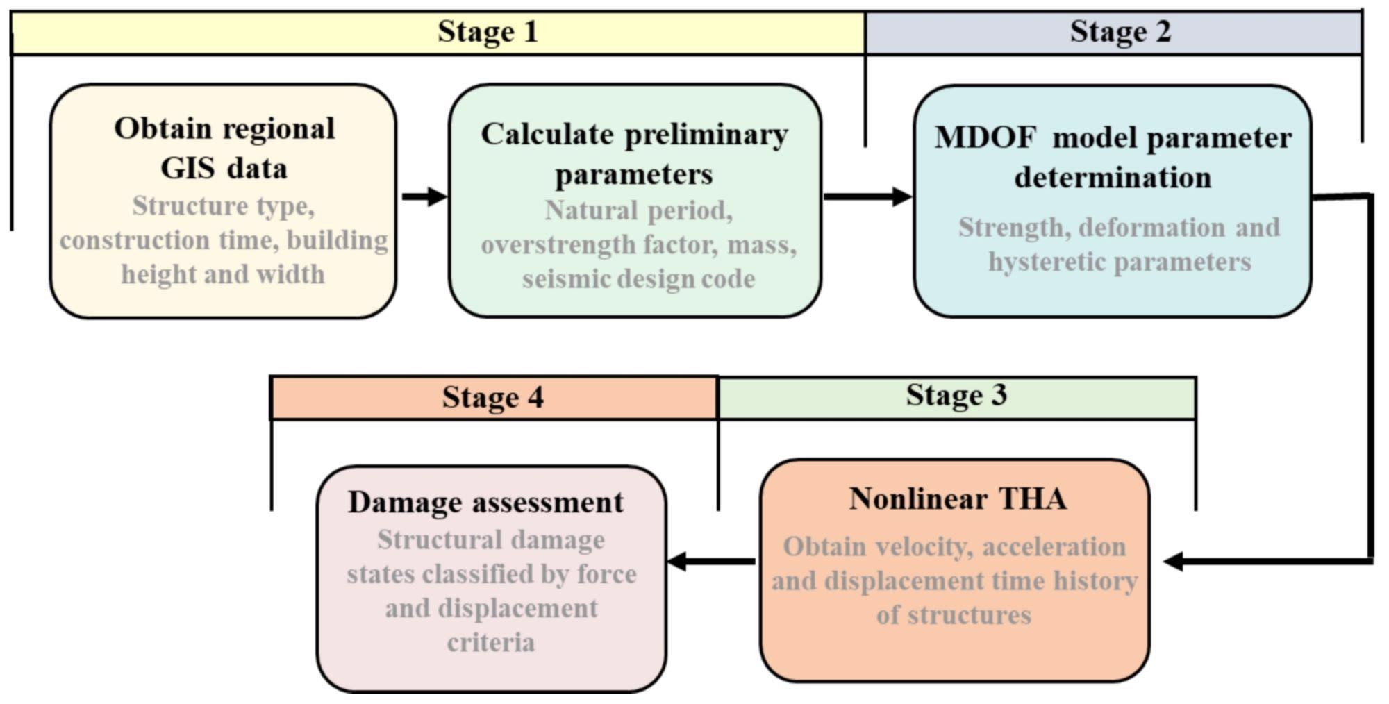
Figure 2. Flowchart of the MCS model analysis. Image Credit: Zhang, et al., 2022
The inter-story force-displacement connections are usually represented using the degenerated three-linearity hysteretic model. The yielding point, peak point, and ultimate point determine the degraded three-linearity hysteretic model.
The overstrength factor is determined by the geometry of the building’s structural parts. To account for the uncertainties, Monte Carlo simulations are used. Table 3 shows a comparison of the models of different MCS-model-based approaches.
Table 3. Comparison of the parameter determination procedures of several MCS models. Source: Zhang, et al., 2022
| Reference |
Proposed by Xu et al. [42] |
Proposed by Wu et al. [43] |
Proposed by Marasco et al. [44] |
| Elastic parameters |
The natural period estimated by empirical equations; stiffness estimated by generalized eigenvalue analysis; design strength estimated by design procedures |
The natural period estimated by empirical equations; stiffness estimated by generalized eigenvalue analysis; design strength estimated by design procedures |
Yield strength and displacement estimated by pushover analysis |
| Inelastic parameters |
Strength estimated by overstrength factors; displacement estimated by strength and stiffness or statistical results |
Strength and displacement estimated by statistical results |
Strength estimated by collapse analysis; displacement estimated by the reduction factor |
Table 4 compares the properties of the proposed design-strength-based technique, MCS model with THA, and improved FE model with THA.
Table 4. Comparison of the proposed method, MCS model with THA, and refined FE model with THA. Source: Zhang, et al., 2022
| |
Design-Strength-Based Method |
MCS Model with THA |
Refined FE Model with THA |
| Computational efficiency |
High |
Moderate |
Low |
| LOD of results |
Overall level |
Floor level |
Component level |
| Required data |
Basic data |
Basic data |
Detailed data |
| Application range |
All types of structures |
Regular structures |
All types of structures |
| General applicability |
A universal method for all structure categories |
A unique model for each structure category |
A unique model for each individual structure |
The design-strength-based method can be used on any structure, including irregular ones, and it requires less data than the other two methods.
When analyzing a building’s seismic reaction using MCS models, identifying an appropriate simplified model and its parameter determination technique for the building category is the first step. Subsequently, conducting the seismic response analysis using the derived MCS model.
The proposed design-strength-based method, on the other hand, applies to buildings of all structure types.
Validation was explored for five reinforced concrete frames with 3-story, 5-story, 8-story, 12-story, and 18-story designs. The buildings’ architectural elevations were comparable. The first story and standard floor heights for each building were 4.2 m and 3.3 m, respectively.
The structural characteristics of the columns and beams of the buildings are shown in Tables 5 and 6.
Table 5. The properties of the columns. Source: Zhang, et al., 2022
| RC Frame |
Stories |
fcu*
(MPa) |
Dimensions (mm) |
Longitudinal Reinforcement |
Transverse Reinforcement |
| Side |
Center |
Side |
Center |
Side |
Center |
| Ratio (%) |
Ratio (%) |
Φ*(mm) |
s*(mm) |
Φ (mm) |
s (mm) |
| 3-story |
1–3 |
30 |
500 × 500 |
500 × 500 |
0.91 |
0.91 |
8 |
100 |
8 |
100 |
| 5-story |
1–5 |
30 |
500 × 500 |
500 × 500 |
0.91 |
0.91 |
8 |
100 |
8 |
100 |
| 8-story |
1–8 |
30 |
550 × 550 |
550 × 550 |
1.09 |
1.09 |
8 |
100 |
8 |
100 |
| 12-story |
1–4 |
35 |
700 × 700 |
700 × 700 |
1.20 |
1.20 |
8 |
100 |
8 |
100 |
| 5–8 |
35 |
600 × 600 |
600 × 600 |
1.27 |
1.27 |
8 |
100 |
8 |
100 |
| 9–12 |
35 |
500 × 500 |
500 × 500 |
1.02 |
1.02 |
8 |
100 |
8 |
100 |
| 18-story |
1–4 |
40 |
700 × 700 |
700 × 700 |
1.20 |
1.20 |
8 |
100 |
8 |
100 |
| 5–10 |
40 |
600 × 600 |
600 × 600 |
1.27 |
1.27 |
8 |
100 |
8 |
100 |
| 11–18 |
40 |
500 × 500 |
500 × 500 |
1.02 |
1.02 |
8 |
100 |
8 |
100 |
* fcu = compressive strength; Φ = diameter of reinforcement bar; s = transverse reinforcement spacing.
Table 6. The properties of the beams. Source: Zhang, et al., 2022
| RC Frame |
Stories |
fcu* (MPa) |
Dimensions (mm) |
Longitudinal Reinforcement Ratio (%) |
Transverse Reinforcement |
| Side |
Center |
Side |
Center |
| Mid-Span |
Bearings |
Mid-Span |
Bearings |
Mid-Span |
Bearings |
Mid-Span |
Bearings |
Φ*
(mm) |
s*
(mm) |
Φ
(mm) |
s
(mm) |
Φ
(mm) |
s
(mm) |
Φ
(mm) |
s
(mm) |
| 3-story |
1–3 |
30 |
250 × 500 |
0.91 |
1.04 |
0.91 |
1.04 |
8 |
100 |
8 |
200 |
8 |
100 |
8 |
200 |
| 5-story |
1–4 |
30 |
250 × 500 |
0.91 |
1.18 |
0.71 |
1.18 |
8 |
100 |
8 |
200 |
8 |
100 |
8 |
200 |
| 5 |
30 |
250 × 500 |
0.91 |
0.81 |
0.71 |
0.81 |
8 |
100 |
8 |
200 |
8 |
100 |
8 |
200 |
| 8-story |
1–5 |
30 |
250 × 600 |
0.72 |
0.98 |
0.72 |
0.98 |
8 |
100 |
8 |
200 |
8 |
100 |
8 |
200 |
| 6–8 |
30 |
250 × 600 |
0.72 |
0.76 |
0.72 |
0.76 |
8 |
100 |
8 |
200 |
8 |
100 |
8 |
200 |
| 12-story |
1–4 |
35 |
300 × 600 |
0.70 |
0.97 |
0.70 |
0.97 |
8 |
100 |
8 |
200 |
8 |
100 |
8 |
200 |
| 5–11 |
35 |
250 × 500 |
1.09 |
1.52 |
1.09 |
1.52 |
8 |
100 |
8 |
200 |
8 |
100 |
8 |
200 |
| 12 |
35 |
250 × 500 |
1.09 |
0.86 |
1.09 |
0.86 |
8 |
100 |
8 |
200 |
8 |
100 |
8 |
200 |
| 18-story |
1–4 |
40 |
300 × 650 |
0.52 |
1.17 |
0.89 |
1.17 |
8 |
100 |
8 |
200 |
8 |
100 |
8 |
200 |
| 5–7 |
40 |
250 × 600 |
0.72 |
1.64 |
1.13 |
1.64 |
8 |
100 |
8 |
200 |
8 |
100 |
8 |
200 |
| 8–10 |
40 |
250 × 600 |
0.72 |
1.64 |
0.91 |
1.64 |
8 |
100 |
8 |
200 |
8 |
100 |
8 |
200 |
| 11–17 |
40 |
250 × 600 |
0.72 |
1.13 |
0.72 |
1.13 |
8 |
100 |
8 |
200 |
8 |
100 |
8 |
200 |
| 18 |
40 |
250 × 600 |
0.72 |
0.63 |
0.72 |
0.63 |
8 |
100 |
8 |
200 |
8 |
100 |
8 |
200 |
* fcu = compressive strength; Φ = diameter of reinforcement bar; s = transverse reinforcement spacing.
As an example, Figure 3 depicts the plan and elevation layout of a three-story structure. The structures were planned to be installed on-site with a shear-wave velocity of (250, 500) m/s and a design peak ground acceleration of 0.15 g, with a 10% chance of exceeding the design in 50 years.
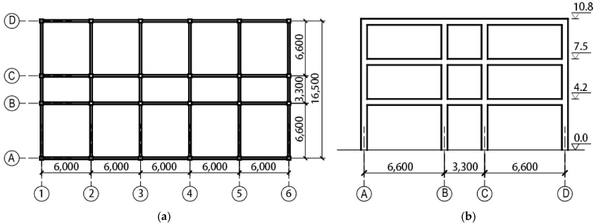
Figure 3. Layouts of the structure (3-story frame as an example): (a) plan layout (unit: mm); (b) elevation layout (unit of elevation: m; unit of bay: mm). Image Credit: Zhang, et al., 2022
The response spectra of six ground motion records from the PEER NGA WEST2 database were shown in Figure 4a, b. The chosen ground motions were well-suited to the target response spectrum.
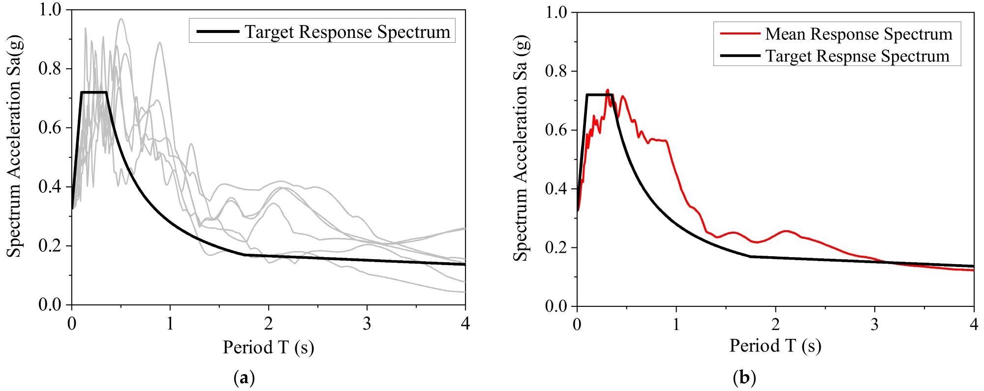
Figure 4. Spectral characteristics of the selected ground motions: (a) each response spectrum and target response spectrum; (b) mean response spectrum and target response spectrum. Image Credit: Zhang, et al., 2022
Table 7 summarizes the basic facts on ground motions.
Table 7. Summary of ground motion records. Source: Zhang, et al., 2022
| No. |
Earthquake Event |
Time |
Component |
Magnitude |
Earthquake Station |
| 1 |
El Centro |
1940 |
180 |
7.0 |
El Centro-lmp Vall lrr Dist |
| 2 |
El Centro |
1940 |
270 |
7.0 |
El Centro-lmp Vall lrr Dist |
| 3 |
Northridge |
1994 |
90 |
6.6 |
TaTzana Cedar Hill Nur.A |
| 4 |
Northridge |
1994 |
360 |
6.6 |
TaTzana Cedar Hill Nur.A |
| 5 |
Chi-Chi Taiwan |
1999 |
E |
7.3 |
KAU082 |
| 6 |
Chi-Chi Taiwan |
1999 |
N |
7.3 |
KAU082 |
The earthquake ground motions were scaled according to the earthquake intensities of common, rare, and extremely rare earthquakes.
Table 8 shows the resulting PGAs and recurrence periods of recurring earthquake intensity, rare earthquake intensity, and extremely rare earthquake intensity levels when the PGA of moderate earthquake intensity is 0.15 g.
Table 8. Earthquake recurrence periods and corresponding PGAs when the PGA of moderate earthquake intensity is 0.15 g. Source: Zhang, et al., 2022
| Earthquake Intensity |
Recurrence Period (Year) |
PGA (g) |
| Frequent earthquake |
50 |
0.056 |
| Rare earthquake |
2475 |
0.316 |
| Extremely rare earthquake |
10,000 |
0.45 |
Figure 5 depicts the inter-story drift ratios of the MCS and refined FE models at three different earthquake intensities.
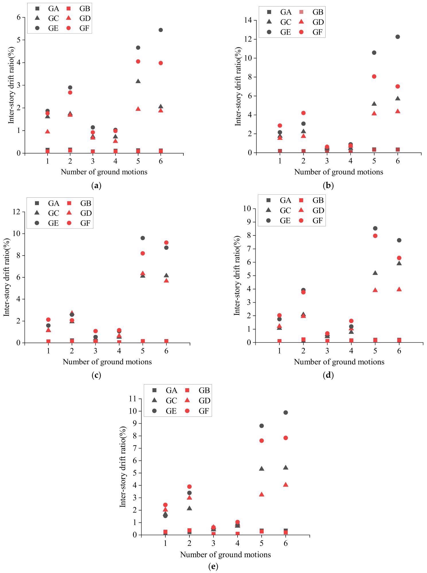
Figure 5. Validation of the MCS-model-based method (maximum IDR): (a) 3-story structure; (b) 5-story structure; (c) 8-story structure; (d) 12-story structure; (e) 18-story structure. Image Credit: Zhang, et al., 2022
GA represents the refined FE model with PGA = 0.056 g, GB represents the MCM model with PGA = 0.056 g, GC represents the refined model with PGA = 0.316 g, GD represents the MCM model with PGA = 0.316 g, GE represents the refined FE model with PGA = 0.45 g and GF represents the MCM model with PGA = 0.45 g.
When the structure’s inter-story ratio is low, the results of the MCM model analysis are more similar to the results of the refined FE model analysis.
The difference between MCS models and refined FE models is that the seismic response of multistory RC frames using the MCS-model-based method is determined by its inter-story force-displacement relationship, which is heavily influenced by the accuracy of the three-linearity hysteretic model parameters.
The MCS models’ seismic damage state assessment criteria are a combination of force-based and deformation-based criteria. Table 9 lists the seismic damage state assessment criteria for the refined FE models developed in the IDARC-2D program.
Table 9. Damage criteria for models built in the IDARC-2D program. Source: Zhang, et al., 2022
| Damage State |
Overall Damage Index |
| No damage |
[0, 0.05) |
| Slight/minor damage |
[0.05, 0.3) |
| Moderate damage |
[0.3, 0.6) |
| Extensive damage |
[0.6, 1) |
| Complete damage |
≥1.0 |
In the software, the five damage states are classified based on the overall structural damage index. Figure 6 depicts the structural damage state results obtained by applying the design-strength-based method.
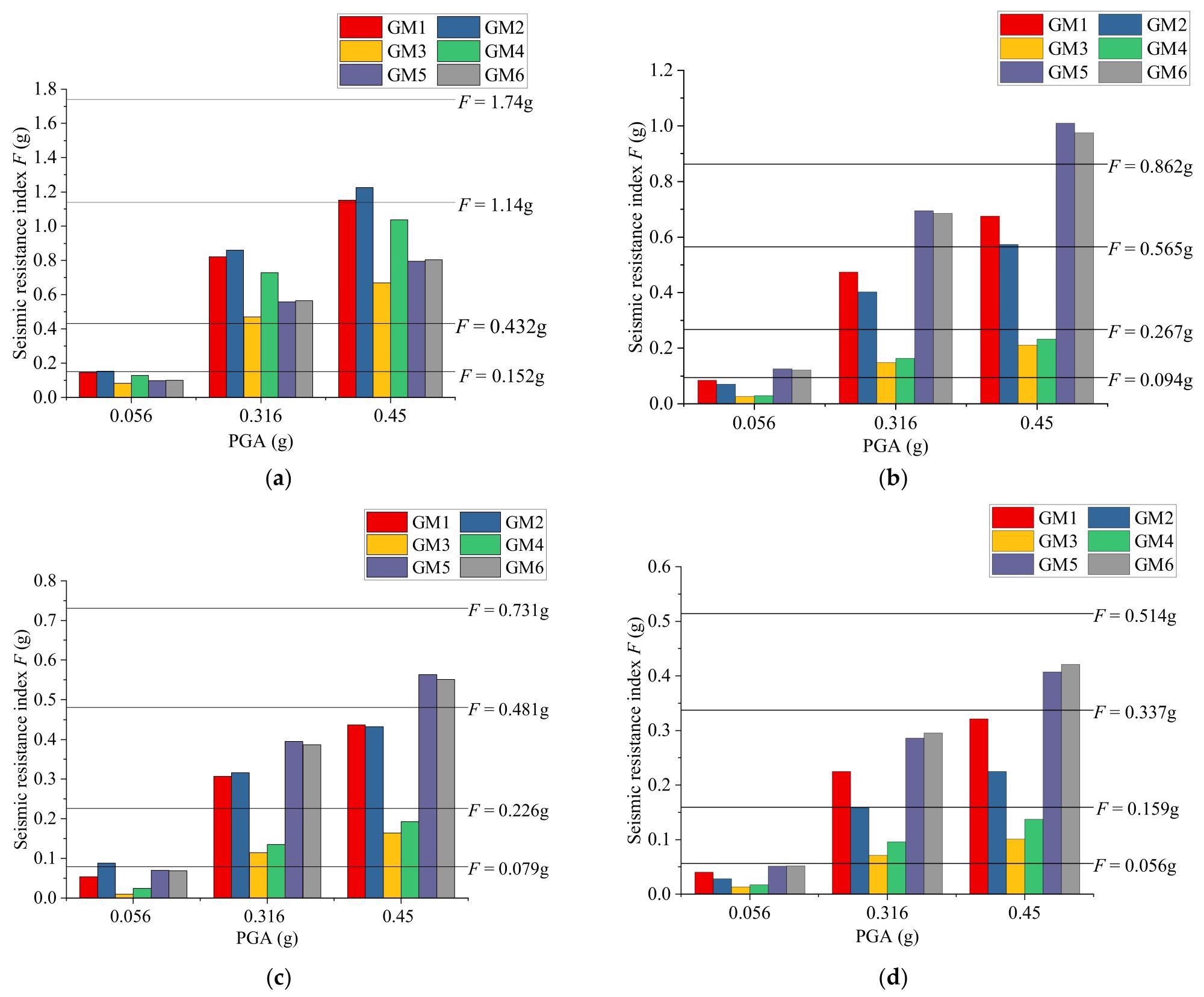
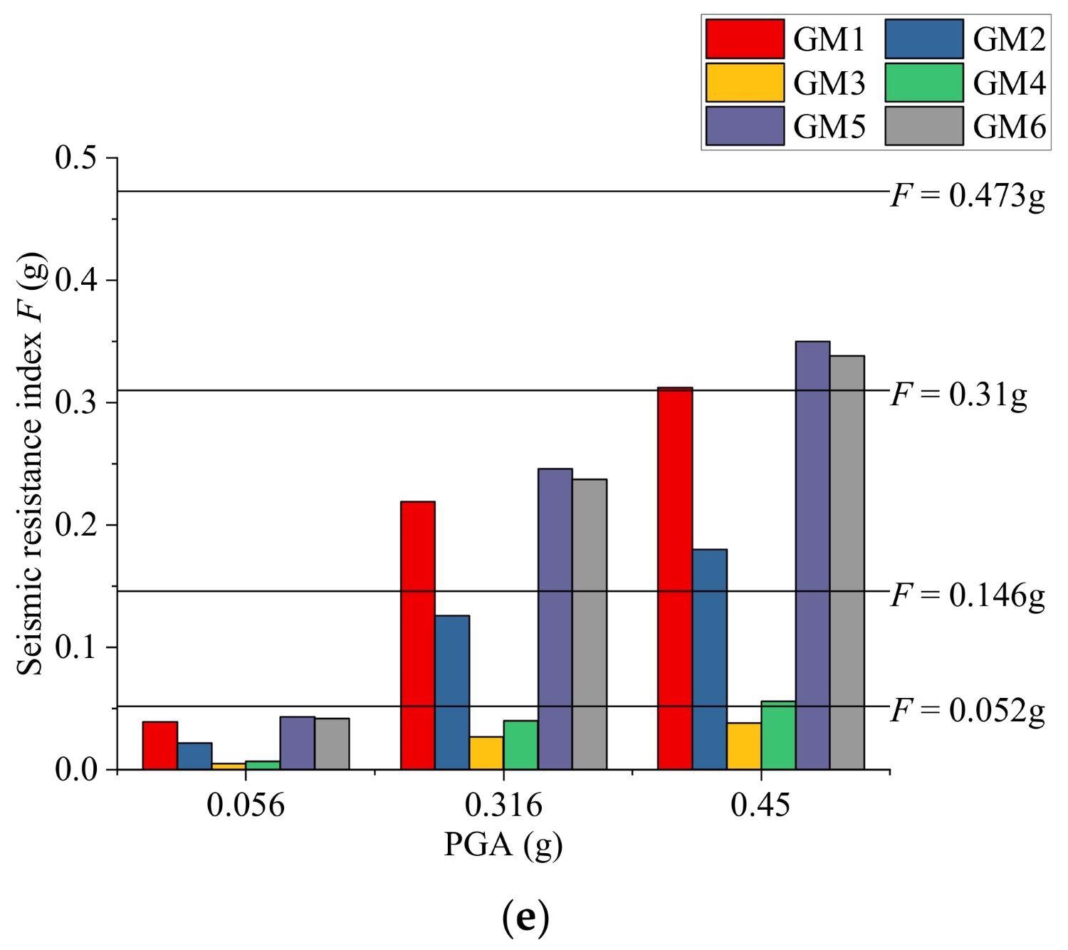
Figure 6. Structural damage states using the proposed design-strength-based method: (a) 3-story structure; (b) 5-story structure; (c) 8-story structure; (d) 12-story structure; (e) 18-story structure. Image Credit: Zhang, et al., 2022
Figure 7 depicts the results of three different seismic damage state prediction methods. In the legend, the letters FE, MCM, and DS represent the refined FE model with THA, the MCM model with THA, and the proposed design-strength-based method, respectively.
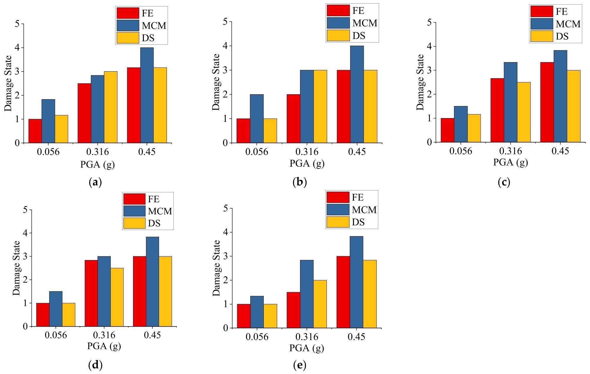
Figure 7. Seismic damage state prediction results using the refined FE model with THA, the MCS model with THA, and the design-strength-based method: (a) 3-story structure; (b) 5-story structure; (c) 8-story structure; (d) 12-story structure; (e) 18-story structure. Image Credit: Zhang, et al., 2022
Figure 8 compares the error between the design-strength-based method and the MCS model with THA, using the refined FE model results as true values. The dispersion coefficient in the range [0, 1] represents the accuracy.
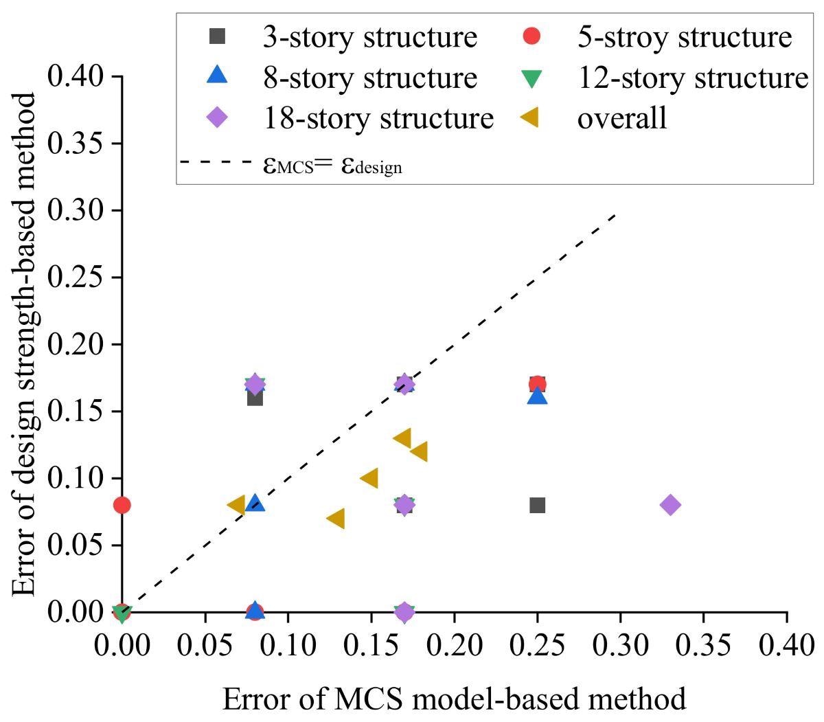
Figure 8. Error of the design-strength-based method and the MCS model with THA, taking the results of the refined FE model with THA as true values. Image Credit: Zhang, et al., 2022
Application
A university campus was used to test the proposed method. The university campus structures were designed in accordance with the seismic design code, and their seismic design PGA is 0.15 g, with a 10% probability of exceeding 50 years. The shear-wave velocity at this location is in the (250, 500) m/s range. Figure 9 depicts a plan view of the campus.
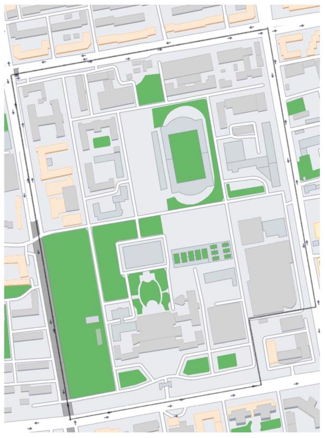
Figure 9. Plan view of the campus. Image Credit: Zhang, et al., 2022
Table 10 displays basic information about the campus’s buildings, such as structural type, number of stories, and construction time. Due to the revision of the Chinese seismic codes, buildings built before 1989 were calculated in the same way as buildings built after 1989.
Table 10. Basic information of the buildings on the investigated campus. Source: Zhang, et al., 2022
| Building Name |
Structural Type |
Number of Stories |
Construction Time |
Building Name |
Structural Type |
Number of Stories |
Construction Time |
| Dorm 1 |
RM |
6 |
1985 |
School building 3 |
RC |
4 |
2002 |
| Dorm 2 |
RM |
6 |
1985 |
School building 4 |
RC |
1 |
2002 |
| Dorm 3 |
RC |
6 |
1998 |
School building 5 |
RC |
5 |
2010 |
| Dorm 4 |
RC |
6 |
1999 |
Lab 2 |
RC |
5 |
2002 |
| Dorm 5 |
RC |
7 |
2001 |
Lab 3 |
RC |
4 |
2010 |
| Dorm 6 |
RC |
7 |
2002 |
Lab 4 |
RM |
4 |
1985 |
| Restaurant 1 |
RC |
2 |
2003 |
Electric building |
RM |
1 |
1985 |
| Restaurant 2 |
RC |
2 |
2003 |
Health center |
RC |
2 |
2002 |
| Restaurant 3 |
RC |
2 |
1998 |
Lab 5 |
RC |
1 |
1985 |
| Restaurant 4 |
RC |
1 |
1999 |
Hospital |
RC |
5 |
2002 |
| Main building |
RC |
10 |
2002 |
Garage |
RM |
5 |
1986 |
| Academic building |
RC |
4 |
1986 |
Lab 6 |
RC |
3 |
2002 |
| Library |
RC |
5 |
2005 |
Activity center |
RC |
1 |
2009 |
| School building 1 |
RC |
6 |
2007 |
Lab 7 |
RC |
5 |
2002 |
| School building 2 |
RM |
5 |
1986 |
|
|
|
|
The proposed design-strength-based method was used to predict the seismic structural damage states of buildings in the case study region. Buildings in the case study area were assumed to have been designed and constructed in strict accordance with design codes.
The average damage conditions of the buildings are shown in Figure 10 for earthquake intensities that are common, rare, and extremely rare.
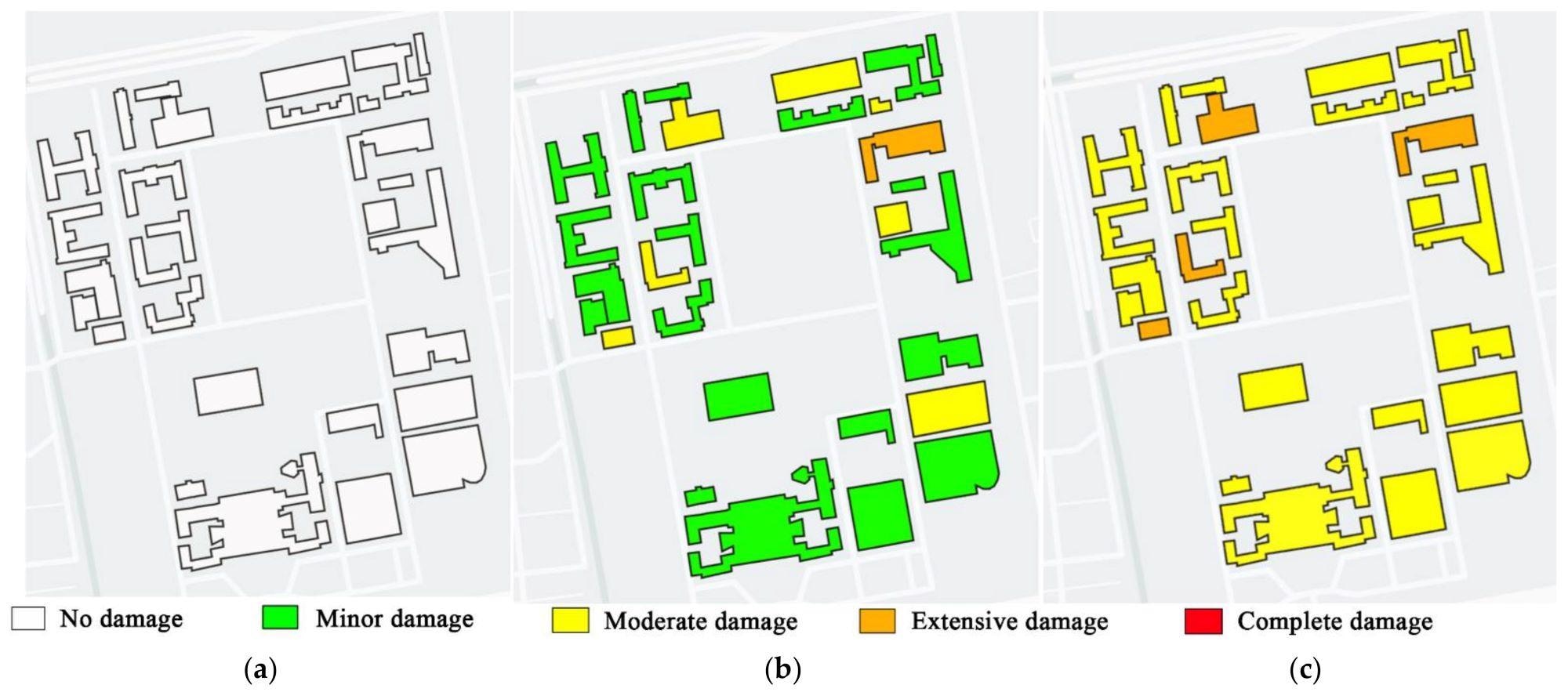
Figure 10. Structural damage states under different earthquake intensities: (a) frequent earthquake; (b) rare earthquake; (c) extremely rare earthquake. Image Credit: Zhang, et al., 2022
The findings show that under regular earthquake intensity, all buildings in the case study region are unaffected, most buildings suffer minor damage under rare earthquake intensity, and most buildings suffer moderate damage under extremely rare earthquake intensity.
The seismic structural damage states show that all of the structures in the case study region meet the design performance targets, implying that the suggested design-strength-based method might provide a good forecast of the building damage state.
Conclusion
This study proposes a quick structural design-strength-based method for predicting seismic damage to urban buildings. To validate the proposed design-strength-based method, five typical RC-frame buildings were subjected to refined FE element model analysis and MCS model analysis.
To show the feasibility and benefits of the suggested technology, the structural seismic damage prediction was applied on a university campus.
By comparing the results of the improved FE model analysis and the MCS model analysis, the proposed method was shown to be both acceptable, accurate, and efficient.
Unlike the MCS-model-based method, the suggested method can theoretically be applied to any type of structure, including irregular structures. Using only a few preliminary parameters of the buildings, the proposed method might offer rapid seismic damage assessment findings for urban buildings, according to the case study.
The objective of this study was to offer a quick method for predicting post-earthquake seismic damage to urban structures. This method is suited for rapid preliminary damage assessment in seismic alarm systems, and it can be used as a guide for government decision-making in emergencies.
The prediction of seismic reaction, including building displacement and acceleration, should be more carefully studied in the future based on structural parameters. As a result, the suggested seismic damage prediction method’s results will be used to assess earthquake losses and casualties as well as predict quick building collapse.
Journal Reference:
Zhang, S., Liu, Y., Li, S. (2022) A Brief Method for Rapid Seismic Damage Prediction of Buildings Based on Structural Strength. Buildings, 12(6), p. 783. Available Online: https://www.mdpi.com/2075-5309/12/6/783/htm
References and Further Reading
- Kajitani, Y., et al. (2013) Economic Impacts of the 2011 Tohoku-Oki Earthquake and Tsunami. Earthquake Spectra, 29(1), pp. S457–S478. doi.org/10.1193%2F1.4000108.
- Imamura, F & Anawat, S (2012) Damage due to the 2011 Tohoku earthquake tsunami and its lessons for future mitigation. In: International Symposium on Engineering Lessons Learned from the 2011 Great East Japan Earthquake, Tokyo, Japan, 1–4 March 2012.
- Hikichi, H., et al. (2016) Can Community Social Cohesion Prevent Posttraumatic Stress Disorder in the Aftermath of a Disaster? A Natural Experiment from the 2011 Tohoku Earthquake and Tsunami. American Journal of Epidemiology, 183(10), pp. 902–910. doi.org/10.1093/aje/kwv335.
- Freddi, F., et al. (2021) Correction to: Observations from the 26th November 2019 Albania earthquake: The earthquake engineering field investigation team (EEFIT) mission. Bulletin of Earthquake Engineering, 19, pp. 2993–2994. doi.org/10.1007/s10518-021-01096-y.
- Miranda, E., et al. (2021) StEER-EERI: Petrinja, Croatia 29 December 2020, Mw 6.4 Earthquake Joint Reconnaissance Report (JRR); In: TTU Libraries, Report No. PRJ-2959; Natural Hazards Engineering Research Infrastructure: West Lafayette, IN, USA. doi.org/10.17603/ds2-1w0y-5080.
- Alcocer, S., et al. (2020) Observations about the seismic response of RC buildings in Mexico City. Earthquake Spectra, 36(2), pp. 154–174. doi.org/10.1177%2F8755293020942523.
- Galvis, F. A., et al. (2020) Overview of collapsed buildings in Mexico City after the 19 September 2017 (Mw7.1) earthquake. Earthquake Spectra, 36(2), pp. 83–109. doi.org/10.1177%2F8755293020936694.
- Mehmet, I., et al. (2021) Application of IOS/Android rapid evaluation of post-earthquake damages in masonry buildings. Gazi Journal of Engineering Sciences, 7(1), pp. 36–50. Available at: https://dergipark.org.tr/en/pub/gmbd/issue/62186/862079
- Fraser William, A., et al. (2008) Using ShakeMap and ShakeCast to Prioritize Post-Earthquake Dam Inspections. In: Geotechnical Earthquake Engineering and Soil Dynamics IV; ASCE Library: Sacramento, CA, USA. doi/abs/10.1061/40975(318)183.
- Silva, V., et al. (2014) Development of the OpenQuake engine, the Global Earthquake Model’s open-source software for seismic risk assessment. Natural Hazards, 72, pp. 1409–1427. doi.org/10.1007/s11069-013-0618-x.
- FEMA. (2012) Multi-Hazard Loss Estimation Methodology HAZUS-MH 2.1 Advanced Engineering Building Module (AEBM) Technical and User’s Manual. In: Federal Emergency Management Agency: Washington, DC, USA; National Institute of Building Science: Washington, DC, USA.
- Martins, L & Silva, V (2021) Development of a fragility and vulnerability model for global seismic risk analyses. Bulletin of Earthquake Engineering, 19, pp. 6719–6745. doi.org/10.1007/s10518-020-00885-1.
- Rojahn, C & Sharpe, R L (1985) Earthquake Damage Evaluation Data for California. In: Applied Technology Council: Redwood City, CA, USA.
- Biglari, M., et al. (2021) Empirical fragility curves of engineered steel and RC residential buildings after Mw 7.3 2017 Sarpol-e-zahab earthquake. Bulletin of Earthquake Engineering, 19, pp. 2671–2689. doi.org/10.1007/s10518-021-01090-4.
- Rosti, A., et al. (2021) Empirical fragility curves for Italian residential RC buildings. Bulletin of Earthquake Engineering, 19, pp. 3165–3183. doi.org/10.1007/s10518-020-00971-4.
- FEMA (1999) Earthquake Loss Estimation Methodology-HAZUS99. In: Federal Emergency Management Agency: Washington, DC, USA; National Institute of Building Science: Washington, DC, USA.
- Alecci, V & De Stefano, M (2019) Building irregularity issues and architectural design in seismic areas. Fracture and Structural Integrity, 13(47), pp. 161–168. doi.org/10.3221/IGF-ESIS.47.13.
- López, S., et al. (2022) Modified Modal Response Spectrum Analysis of Plan Irregular Highly Torsionally-Stiff Structures Under Seismic Demands. In: Seismic Behaviour and Design of Irregular and Complex Civil Structures IV; Springer: Cham, Switzerland, 2022; pp. 311–320. doi.org/10.1007/978-3-030-83221-6_26
- Alecci, V., et al. (2019) Evaluation of the American Approach for Detecting Plan Irregularity. Advances in Civil Engineering, 2019, p. 2861093. doi.org/10.1155/2019/2861093.
- Powell, G H & Allahabadi, R (1988) Seismic damage prediction by deterministic methods: Concepts and procedures. Earthquake Engineering & Structural Dynamics, 16(5), pp. 719–734. doi.org/10.1002/eqe.4290160507.
- Khaloo, A R & Khosravi, H (2013) Modified fish-bone model: A simplified MDOF model for simulation of seismic responses of moment resisting frames. Soil Dynamics and Earthquake Engineering, 55, pp. 195–210. doi.org/10.1016/j.soildyn.2013.09.013.
- Soleimani, R., et al. (2019) Substitute Frame and adapted Fish-Bone model: Two simplified frames representative of RC moment resisting frames. Engineering Structures, 185, pp. 68–89. doi.org/10.1016/j.engstruct.2019.01.127.
- Xiong, C., et al. (2017) Parameter Determination and Damage Assessment for THA-Based Regional Seismic Damage Prediction of Multi-Story Buildings. Journal of Earthquake Engineering, 21(3), pp. 461–485. doi.org/10.1080/13632469.2016.1160009
- Xiong, C., et al. (2016) A nonlinear computational model for regional seismic simulation of tall buildings. Bulletin of Earthquake Engineering, 14, pp. 1047–1069. doi.org/10.1007/s10518-016-9880-0.
- Marasco, S., et al. (2021) A computational framework for large-scale seismic simulations of residential building stock. Engineering Structures, 244, p. 112690. doi.org/10.1016/j.engstruct.2021.112690.
- D’Aragona, M. G., et al. (2020) Stick-IT: A simplified model for rapid estimation of IDR and PFA for existing low-rise symmetric infilled RC building typologies. Engineering Structures, 223, p. 111182. doi.org/10.1016/j.engstruct.2020.111182.
- Bose, S & Stavridis, A (2022) A computationally efficient framework for the simulation of the nonlinear seismic performance of infilled RC frame buildings. Engineering Structures, 259, p. 114039. doi.org/10.1016/j.engstruct.2022.114039
- Gusella, F., et al. (2019) Influence of mechanical and geometric uncertainty on rack connection structural response. Journal of Constructional Steel Research, 153, pp. 343–355. doi.org/10.1016/j.jcsr.2018.10.021.
- Bian, G., et al. (2017) Reliability of cold-formed steel framed shear walls as impacted by variability in fastener response. Engineering Structures, 142, pp. 84–97. doi.org/10.1016/j.engstruct.2017.03.072.
- Lu, X., et al. (2017) Parametric sensitivity study on regional seismic damage prediction of reinforced masonry buildings based on time-history analysis. Bulletin of Earthquake Engineering, 15, pp. 4791–4820. doi.org/10.1007/s10518-017-0168-9.
- Harirchian, E., et al. (2021) A review on application of soft computing techniques for the rapid visual safety evaluation and damage classification of existing buildings. Journal of Building Engineering, 43, p. 102536. doi.org/10.1016/j.jobe.2021.102536.
- Allali, S. A., et al. (2018) Post-earthquake assessment of buildings damage using fuzzy logic. Engineering Structures, 166, pp. 117–127. doi.org/10.1016/j.engstruct.2018.03.055
- Harirchian, E & Lahmer, T (2020) Improved rapid assessment of earthquake hazard safety of structures via artificial neural networks. IOP Conference Series: Materials Science and Engineering, 897, p. 012014. doi.org/10.1088/1757-899X/897/1/012014.
- Kumari, V., et al. (2022) Evaluation of Machine Learning and Web-Based Process for Damage Score Estimation of Existing Buildings. Buildings, 12(5), p. 578. doi.org/10.3390/buildings12050578.
- Xu, S & Noh, H Y (2021) PhyMDAN: Physics-informed knowledge transfer between buildings for seismic damage diagnosis through adversarial learning. Mechanical Systems and Signal Processing, 151, p. 107374. doi.org/10.1016/j.ymssp.2020.107374.
- FEMA (2012) Multi-Hazard Loss Estimation Methodology: Earthquake Model. In: Federal Emergency Management Agency, National Institute of Building Science: Washington, DC, USA.
- Lin, S., et al. (2010) Performance-based methodology for assessing seismic vulnerability and capacity of buildings. Earthquake Engineering and Engineering Vibration, 9, pp. 157–165. doi.org/10.1007/s11803-010-0002-8.
- Lu, X & Guan, H (2021) Earthquake Disaster Simulation of Civil Infrastructures. In: 2nd ed.; Springer: Beijing, China. Available at: https://link.springer.com/book/10.1007/978-981-10-3087-1
- GB50010-2010; (2010) Code for Seismic Design of Buildings. Ministry of Housing and Urban-Rural Development of P. R. China: Beijing, China.
- GB18306-2015; (2015) Seismic Ground Motion Parameter Zonation Map of China. Ministry of Housing and Urban-Rural Development of P. R. China: Beijing, China.
- Lu, D., et al. (2018) Uniform risk-targeted definitions and decision-making of four seismic design levels con-sidering very rare earthquake. China Civil Engineering Journal, 51(11), pp. 41–52. Available at: https://www.researchgate.net/publication/332260336_Uniform_risk-targeted_definitions_and_decision-making_of_four_seismic_design_levels_considering_very_rare_earthquake
- Xu, Z., et al. (2014) Seismic damage simulation in urban areas based on a high-fidelity structural model and a physics engine. Natural Hazards, 71, p. 1679–1693. doi.org/10.1007/s11069-013-0972-8.
- Wu, K., et al. (2017) Study on backbone curves of rc frame model for simulation of city-scale seismic responses of buildings. In: 26th National Structural Engineering Conference, Changsha, China, 22–24 September.
- Marasco, S., et al. (2017) Resilience assessment for the built environment of a virtual city. In: 6th ECCOMAS Thematic Conference on Computational Methods in Structural Dynamics and Earthquake Engineering, Rhodes Island, Greece, 15–17 June 2017; pp. 1–13. Available at: https://2017.compdyn.org/proceedings/pdf/18180.pdf
- Zhai, C., et al. (2009) Inelastic displacement ratio spectra for reinforced concrete regular frame structures. Engineering Mechanics, 26(9), pp. 80–86. Available at: https://www.engineeringmechanics.cn/en/article/id/697
- Sun, Y (2006) Study on the Inelastic Displacement Estimation of Aseismatic Structures. Master’s Thesis, Harbin Institute of Technology, Harbin, China.
- Reinhorn, A. M., et al. (2010) IDARC2D Version 7.0: A Program for the Inelastic Damage Analysis of Structures. In: Multidisciplinary Center for Earthquake Engineering Research (MCEER): Buffalo, NY, USA. Available at: https://www.buffalo.edu/mceer/catalog.host.html/content/shared/www/mceer/publications/MCEER-09-0006.detail.html