Tabique walls (TWs) are found in old constructions/buildings in Portugal. This article, drawing on research in the journal Architecture, Structures and Construction, investigates the TWs to provide more insight into their construction mechanisms and the materials used.
Tabique Walls (TWs) are light timber walls made of diagonal and/or vertical boards filled in and covered with mortar. They are found in old buildings in Portugal, mostly inside the buildings, and serve as partition walls. Most experts consider them insignificant.
The current study puts forth the results of an analysis of TWs, which aids in understanding the value of this technique. The investigation complemented the study on the assessment of the mechanical behavior of TWs by shear-compression and compression tests on full-scale specimens in the lab and in situ.
A better understanding of the materials and mechanisms employed in its construction is a better means to evade inadequate and even disproportionate rehabilitation interventions. The gathered information refers to the location of TWs in the buildings, their material and geometrical characteristics, and construction details.
The analysis included 11 buildings representative of vernacular architecture. And these buildings had two to three floors and are mostly residential. (see Figure 1a and b).
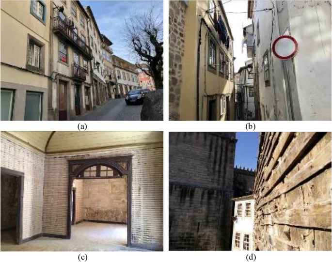
Figure 1. Examples of the built heritage in the historic center of Viseu, (a) and (b), with interior (c) and exterior (d) tabique walls. Image Credit: José Padrão
The exterior and the interior walls of the building in contact with the ground are of granite stone masonry (see Figure 2a and b). The floors and roof structure are of solid timber, and the roofs are covered with ceramic tiles, and the walls are covered with mortar.
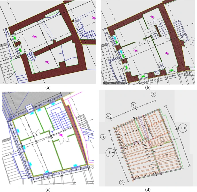
Figure 2. Example of a building with TWs: architectural plans of the (a) basement, (b) ground floor, (c) upper floor, and (d) structural plan of the upper floor. Image Credit: José Padrão
Figure 2 illustrates the architectural and structural plans of an upper floor. The buildings investigated were under deep rehabilitation works which resulted in a partial or total demolition of the inside.
Tabique Walls’ Characterization
Most traditional construction techniques use natural resources. Timber being largely available, resistant, light and easy working material were used extensively in constructions worldwide.
The TWs follow a light timber wall variant technique. The main structure has vertical, or vertical and diagonal boards and metallic connectors.
TWs depended on the local resources and the knowledge of the builders, similar to all traditional techniques.
Solid timber is the major component providing resistant capacity to the TWs. Four variants of the most common TWs typologies were observed in the buildings and Table 1 shows a brief description along with a reference picture.
Table 1. TWs’ classification according to their constructive typology. Source: José Padrão
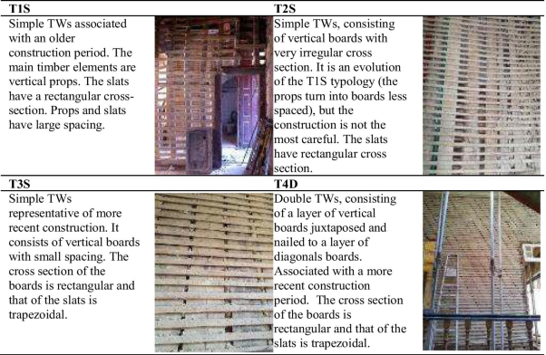
The typologies showed distinct variations and the variation was most notable between T1S and others. The TWs construction system underwent changes and involved modifications. Table 2 depicts the major evolutionary differences identified.
Table 2. Differences between older and latter construction systems. Source: José Padrão
| Older building system |
Latter construction system |
| Wood elements |
- Vertical elements have smaller width (cross-section closer to a square—props) and larger spacing
- The slats have a higher width and spacing, and a rectangular cross-section
|
- Vertical elements are much larger than thick (boards) and have small spacing
- Slats have smaller width and smaller spacing, and a rectangular or, the most usual, trapezoidal cross-section
|
| Note: the most recent TWs present a more careful choice of the elements (more homogeneous sections, especially in the better-constructed TWs) |
| Mortar |
- Earth based mortars with larger particles (stones, construction waste, etc.)
- Use of elements of vegetal origin, such as straw, to improve cohesion
|
- More homogeneous earth-based mortars
- Use of lime to improve cohesion
|
| Metallic connectors |
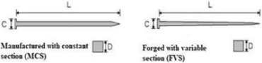
- Use of forged steel connectors, manufactured in small local workshops
- Connectors have variable section
|
- Use of low carbon steel connectors, industrially manufactured
- Connectors have constant section
|
The 11 buildings were grouped into two to study the differences in the construction technique of TWs. Figure 6 illustrates an example of buildings inspected in each group.
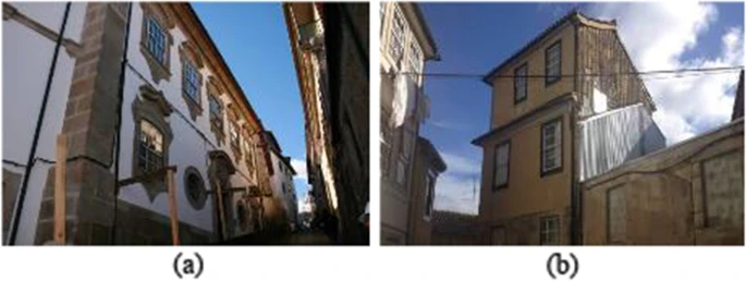
Figure 6. Inspected buildings belonging to (a) Group I e (b) Group II. Image Credit: José Padrão
Table 3 lists the average dimensions of the evaluated timber elements and Figure 7 illustrates the nomenclature.
Table 3. Timber boards dimensions, by type of construction. Source: Padrão, et al., 2021
| Comparison by constructive typology |
| Typology |
Vertical / diagonal boards (mm; º) |
Slats (mm) |
| A1 |
A2 |
B1 |
B2 |
C1 |
C2 |
α (º) |
D |
E |
F |
| Simple Tabique Walls |
| T1S |
| Group I |
80 |
– |
68 |
– |
231 |
– |
– |
55 |
12 |
56 |
| Group II |
95 |
– |
– |
– |
277 |
– |
– |
65 |
17 |
96 |
| T2S |
| Group I |
173 |
– |
50 |
– |
41 |
– |
– |
29 |
11 |
46 |
| Group II |
130 |
– |
46 |
– |
52 |
– |
– |
36 |
11 |
45 |
| T3S |
| Group I |
189 |
– |
51 |
– |
25 |
– |
– |
40 |
14 |
49 |
| Group II |
136 |
– |
55 |
– |
36 |
– |
– |
37 |
12 |
44 |
| Double Tabique Walls |
| T4D |
| Group I |
184 |
197 |
62 |
34 |
43 |
24 |
27 |
34 |
14 |
38 |
| Group II |
179 |
220 |
55 |
34 |
30 |
23 |
32 |
34 |
14 |
38 |
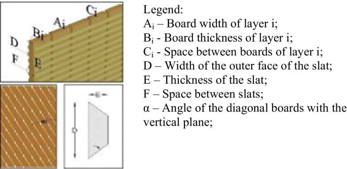
Figure 7. Nomenclature used in the measurement of TWs’ timber boards in Table 3. Image Credit: José Padrão
A specific feature of simple TWs in the Viseu region is the use of diagonal boards or props. Numerous constructive dispositions were observed and were organized into four major groups (see Figure 8).
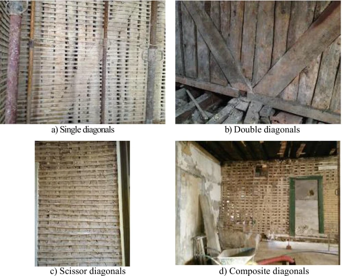
Figure 8. Constructive disposition for diagonal boards. Image Credit: José Padrão
Construction Details
The connections between the different timber elements and the other structural elements play a significant role in the complete structural behavior of the building. A change in the kind of metallic connectors used was noticed. Figure 9 depicts the change in the shape of nails used.
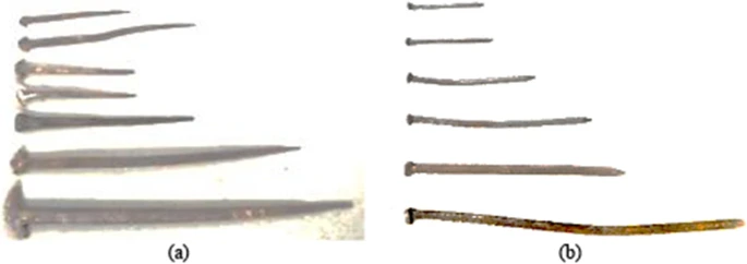
Figure 9. Evolution of nails/dowels used (a) in old TWs and (b) in more recent TWs. Image Credit: José Padrão
The size and type of nails and dowels linked to their function are listed in Table 4.
Table 4. Dimensions of metallic connectors (nails / dowels). Source: Padrão, et al., 2021
 |
| Connection type |
Building |
No. of samples |
Typology |
Dimensions—Average values (mm) |
| Length (L) |
Connector Head (C) |
Cross section (D) |
| CT1 |
Bd 1 |
14 |
MCS |
24,2 |
2,2 |
1,0 |
| CT2 |
Bd 1 |
9 |
FVS |
88,3 |
12,2 |
4,8 (*) |
| CT3 |
Bd 1 |
28 |
MCS |
45,8 |
5,6 |
2,3 |
| Bd 2 |
11 |
MCS |
59,6 |
7,1 |
3,8 |
| Bd 3 |
11 |
MCS |
46,6 |
5,2 |
2,4 |
| CT4 |
Bd 3 |
10 |
MCS |
89,6 |
7,1 |
3,6 |
| CT5 |
Bd 3 |
9 |
MCS |
66,6 |
6,7 |
3,0 |
| CT6 |
Bd 3 |
9 |
MCS |
81,4 |
6,7 |
3,3 |
| CT7 |
Bd 1 |
9 |
FVS |
86,9 |
6,2 |
4,2 (*) |
| Bd 2 |
18 |
FVS |
96,7 |
11,9 |
6,4 (*) |
| Bd 3 |
9 |
MCS |
109,1 |
7,8 |
4,1 |
| CT8 |
Bd 3 |
3 |
MCS |
152,2 |
10,4 |
5,4 |
| CT9 |
Bd 2 |
4 |
FVS |
72,9 |
18,6 |
5,9 (*) |
| CT10 |
Bd 1 |
5 |
FVS |
171,8 |
16,8 |
8,7 (*) |
Building Bd 1 – Travessa Escadinhas da Sé, n.º 24
Building Bd 2 – Praça D. Duarte, n. º 11 e 13 (*) – mid-section
Building Bd 3 – Gaveto das Ruas Formosa, Dr. Luís Ferreira e Direita
Connection CT 1: On TW boards to improve adhesion with the coating mortar
Connection CT 2: On the boards of external TW for fixing ceramic covering elements
Connection CT 3: Between vertical boards and slats
Connection CT 4: Between vertical boards and secondary elements (baseboards, etc.) of higher thickness
Connection CT 5: Between vertical boards and secondary elements (baseboards, etc.) of lower thickness
Connection CT 6: Between vertical boards and jambs
Connection CT 7: Between vertical boards and top beams
Connection CT 8: Between TW perpendicular to each other (on vertical boards)
Connection CT 9: To fix metal plates to vertical boards, in the connection between TW and masonry walls
Connection CT 10: Between floor beams and TW beams
Beams link the TWs boards together and to the floor structure. They could be of any shape (see Figure 10).
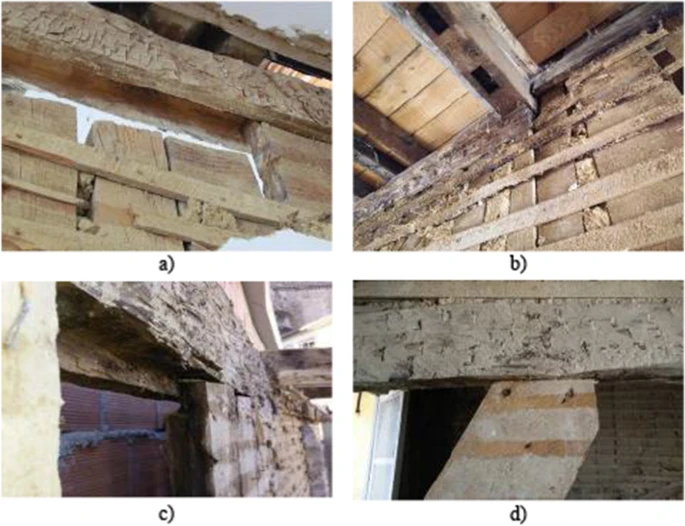
Figure 10. Connections between TWs boards and top beams: (a) with a continuous groove; (b) with a discontinuous groove; (c) with lateral groove and (d) without groove. Image Credit: José Padrão
Certain diversity was noted in the connection between the floor structure and the vertical elements as seen in Figure 11.
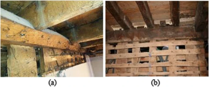
Figure 11. Connection between the floor beams and the TWs: (a) with notch or (b) without notch. Image Credit: José Padrão
Two alternative arrangements were noted between the interior TWs and granite masonry walls as seen in Figure 12.
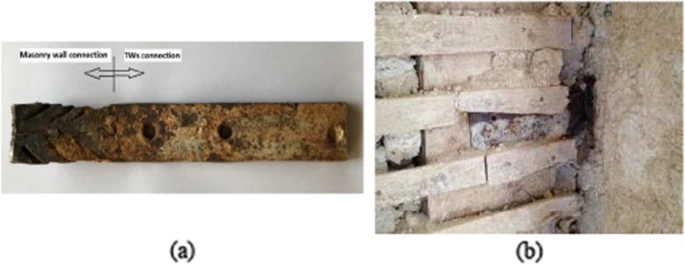
Figure 12. Connection between TW and masonry walls: (a) metallic plate; (b) constructive detail. Image Credit: José Padrão
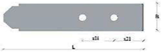
Table 5 depicts the geometrical characteristics of the connection plates between 12 TWs and stone masonry walls.
Table 5. Dimension of the connecting metallic plates, between TW and masonry walls. Source: Padrão, et al., 2021
 |
| |
No. of samples |
Dimensions—Average values (mm) |
| Length (L) |
Width (B) |
Thickness |
Distance between holes (x1i) |
Distance between holes and edge (x21) |
| Connecting plates |
15 |
163 |
37 |
6 |
52 |
21 |
Experimental Characterization of Material Properties
As a fundamental step to investigate the structural behavior of TWs and of the buildings that integrate them, the constituent materials—wood, mortar, and metallic connectors were characterized.
The timber elements are the “structural skeleton” of TWs. It was found that pine (Pinus pinaster Ait.) was used extensively and occasionally chestnut (Castanea sativa Mill.) was seen. The mechanical and physical properties of the wood specimens were analyzed (see Figure 13).
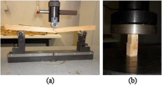
Figure 13. Mechanical tests on wood: (a) static bending; (b) axial compression (parallel to fibers). Image Credit: José Padrão
The values obtained from the tests for the two wood species are shown in Table 6.
Table 6. Experimental values obtained in tests on timber elements. Source: Padrão, et al., 2021
| Properties |
Building 1 |
Building 2 |
Building 3 |
| Average value |
COV |
Average value |
COV |
Average value |
COV |
| Compression parallel to fibres |
| Species: Pine wood (Pp) |
| Number of samples tested |
22 |
25 |
34 |
| Water content, H (%) |
11,99 |
6,1% |
9,00 |
3,0% |
11,13 |
1,7% |
| Ultimate stress, fc,0 (N/mm2) |
62 |
7,8% |
47 |
9,4% |
40 |
8,9% |
| Reference density, ρ12 (kg/m3) |
665 |
7,9% |
572 |
4,3% |
565 |
6,9% |
| Species: Chestnut (Cs) |
| Number of samples tested |
|
|
25 |
| Water content, H (%) |
|
|
|
|
9,58 |
1,9% |
| Ultimate stress, fc,0 (N/mm2) |
|
|
|
|
46 |
12,8% |
| Reference density, ρ12 (kg/m3) |
|
|
|
|
572 |
8,7% |
| Static bending |
| Species: Pine wood (Pp) |
| Number of samples tested |
10 |
10 |
17 |
| Ultimate stress, fm (N/mm2) |
141 |
8,9% |
123 |
13,1% |
94 |
14,9% |
| Flexural Young modulus, Em,0 (N/mm2) |
10,926 |
9,0% |
8995 |
15,6% |
4478 |
8,5% |
| Reference density, ρ12 (kg/m3) |
634 |
4,1% |
647 |
6,4% |
565 |
6,9% |
| Species: Chestnut (Cs) |
| Number of samples tested |
|
|
|
|
13 |
| Ultimate stress, fm (N/mm2) |
|
|
|
|
123 |
14,9% |
| Flexural Young modulus, Em,0 (N/mm2) |
|
|
|
|
9257 |
12,9% |
| Reference density, ρ12 (kg/m3) |
|
|
|
|
572 |
8,7% |
| Hardness (Chalais-Meudon Method) |
| Species: Pine wood (Pp) |
| Number of samples tested |
10 |
15 |
17 |
| Hardness |
4,3 |
29,6% |
2,6 |
20,4% |
4,4 |
28,7% |
| Species: Chestnut (Cs) |
| Number of samples tested |
|
|
|
|
19 |
| Hardness |
|
|
|
|
2,5 |
31,8% |
| COV: Coefficient of variation |
|
|
|
|
|
|
Mortar is a secondary element in TWs with filling and coating purposes, along with protecting the timber structure. Characterization of these elements was carried out. Figure 14 illustrates the granulometric curves of mortars.
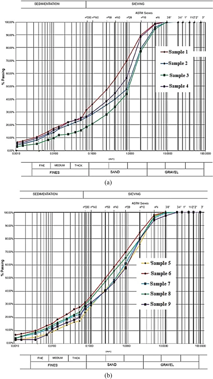
Figure 14. Granulometric curves of the mortar samples belonging to (a) Building 1 and (b) Building 2. Image Credit: José Padrão
SEM/ EDS analysis was carried out and Figure 15 illustrates the results of two samples. It was seen that the filling material was harder and was difficult to smash with the fingers.
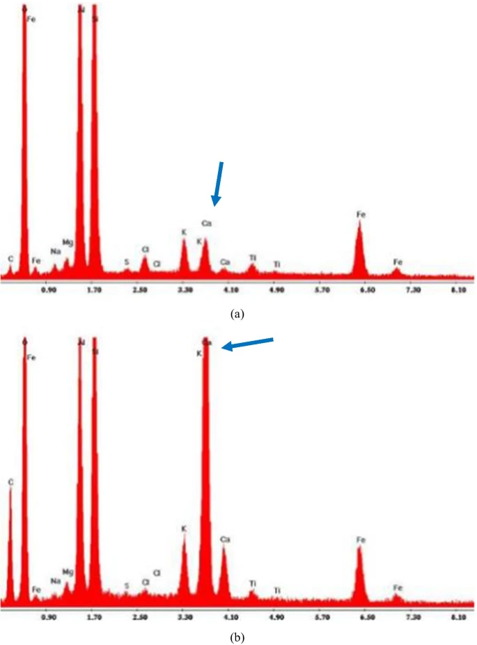
Figure 15. Type spectra obtained by SEM / EDS analysis in mortar samples (a) without calcium and (b) with calcium. Image Credit: José Padrão
Metallic connectors found in TWs play a significant role. They connect the various elements of the TWs.
Two mechanical tests (tension and Vickers microhardness) were performed on the samples removed from the TWs. Table 7 lists the observations of the tensile tests on the metal connectors.
Table 7. Results obtained in the tensile test of metallic connectors. Source: Padrão, et al., 2021
| Sample |
Fmax [kN] |
Umax [mm] |
fmax [N/mm2] |
| Nails / Dowels |
|
|
|
| 5.1 |
8,63 |
0,31 |
313,85 |
| 5.2 |
15,87 |
10,86 |
387,57 |
| 5.3 |
8,61 |
6,56 |
337,57 |
| 5.4 |
23,07 |
15,80 |
339,02 |
| 5.5 |
5,68 |
11,96 |
354,86 |
| 5.6 |
28,24 |
10,63 |
464,50 |
| 5.7 |
12,67 |
1,29 |
335,42 |
| 1.1 |
8,69 |
1,90 |
365,85 |
| 1.2 |
16,46 |
4,06 |
351,18 |
| 1.3 |
8,53 |
9,43 |
333,47 |
| 1.4 |
11,37 |
9,50 |
389,78 |
| 1.5 |
14,37 |
8,26 |
362,23 |
| 1.6 |
9,98 |
7,03 |
348,80 |
| 1.7 |
9,43 |
5,66 |
348,67 |
| Average value |
|
|
359,48 |
| COV (%) |
|
|
10,16% |
| Metallic plates |
|
|
|
| 1 |
25,73 |
13,96 |
382,90 |
| 2 |
23,05 |
3,77 |
374,86 |
| 3 |
24,46 |
11,40 |
331,75 |
| 4 |
19,14 |
8,96 |
322,23 |
| 5 |
79,92 |
12,40 |
467,35 |
| 6 |
33,96 |
8,00 |
393,05 |
| 7 |
51,54 |
9,56 |
526,18 |
| 8 |
18,71 |
3,66 |
359,72 |
| 9 |
41,72 |
12,76 |
447,81 |
| 10 |
24,07 |
11,71 |
383,53 |
| Average value |
|
|
398,94 |
| COV (%) |
|
|
15,92% |
COV Coefficient of variation
In the nomenclature of the samples of metal plates, the first index refers to the building identification and the second index refers to the number of the sample
Figure 16 shows the stress-displacement plots for all the samples tested.
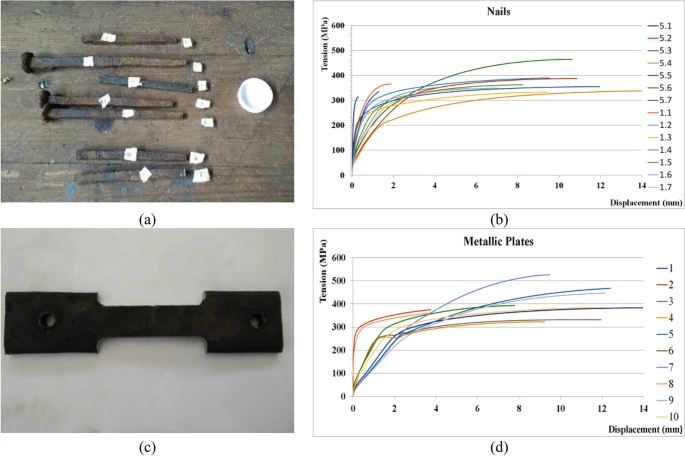
Figure 16. Tensile tests: (a) nails’ samples before preparation, (b) stress-displacement results of nails’ tests and (c) metallic plate sample after preparation, (d) stress-displacement results of metallic plates’ tests. Image Credit: José Padrão
The Vickers microhardness test was carried out and the observations are listed in Table 8.
Table 8. Results obtained from the Vickers microhardness test (HV 10). Source: Padrão, et al., 2021
| HV 10 |
Samples (average values) |
Global
average |
Standard
deviation |
COV
(%) |
| 1 |
2 |
3 |
4 |
5 |
6 |
7 |
| Without inclusions |
161 |
160 |
145 |
124 |
169 |
131 |
158 |
150 |
16 |
10,43 |
| With inclusions |
168 |
175 |
132 |
137 |
179 |
139 |
169 |
157 |
18 |
11,75 |
Microstructural analysis carried out depicted the presence of inclusions (see Figure 17). Also, the presence of two phases in the manufacturing process—ferrite and perlite—was observed.
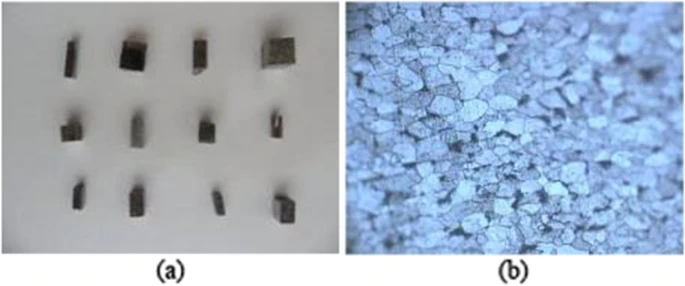
Figure 17. Microstructural analysis (a) sample preparation and (b) sample surface (longitudinal direction). Image Credit: José Padrão
Discussion
Portugal had numerous tabique walls (TWs) which disappeared gradually. This article inspected 11 buildings representing the construction systems characteristic of the Viseu region.
The study created TW typologies and analyzed particular characteristics. Further investigation on the constituent elements and materials revealed much vital information like the timber elements are made of pine.
The characterization tests revealed that the mortar had an extensive granulometric curve and that it was made up of silty sand. The metallic connectors showed great geometric variability depending on the place applied. Tests revealed that they were constituted by a forged steel metallic alloy.
Conclusion
The investigation results on TWs—geometric data, construction details, and experimental results—are crucial information for professionals and researchers in the field of intervention/ rehabilitation of old buildings. These observations could enhance the understanding of this construction system found in Portugal so that the TWs do not lose their uniqueness during rehabilitation.
Journal Reference:
Padrão, J., Guedes, J., Pinto, J., Arêde, A. (2021) Tabique walls, a light timber structure – constructive details and material characterization. Architecture, Structures and Construction, 51. Available online: https://link.springer.com/article/10.1007/s44150-021-00010-z#citeas
References and Further Reading
Amorim, M., et al. (2018) Experimental assessment of in-plane mechanical behavior of tabique walls. International Journal of Architectural Heritage, 12(4), pp. 516–532. doi.org/10.1080/15583058.2018.1442514.
- Amorim, M., et al. (2019) Avaliação experimental do comportamento mecânico de paredes de tabique. Revista Portuguesa de Engenharia de Estruturas, Série III Nº 10, pp 51–62. LNEC, Lisbon. ISSN 2183-8488.
- Carvalho, J., et al. (2008) Construções em Tabique na região de Trás-os-Montes e Alto Douro. In: CINPAR 2008 – 4th International Conference on Structural Defects and Repair. Civil Engineering Department, University of Aveiro, Portugal, June, pp. 25–28. Varum, H., et al. (Eds). ISBN: 978-989-95695-3-9.
- Cepeda, A., (2010) Tabique construction in Alto Tâmega. Book of abstracts of the 1st International Conference on Structures and Architecture (ICSA2010). Bd. Paulo Cruz. CRC Press, Taylor & Francis Group, London, pp 397–398. ISBN 978-0-415-49249-2.
- E 196 (1966) Solos - Análise granulométrica. Laboratório Nacional de Engenharia Civil, Lisboa.
- Graham T (2003) Wattle and Daub: Craft, Conservation and Wiltshire Case Study. Master’s degree thesis in Conservation of Historic Building. Universidade de Bath. Department of Architecture and Civil Engineering. Available at: http://www.tonygraham.co.uk/house_repair/wattle_daub/WD.html (Accessed 16 March 2020).
- ICOMOS - International Scientific Committee for Analysis and Restoration of Structures of Architectural Heritage (2003) Recommendations for the analysis, conservation and structural restoration of architectural heritage. Edited by International Scientific Committee for Analysis and Restoration of Structures of Architectural Heritage of ICOMOS. ICOMOS, Lisboa.
- Memoiredelivrade (2020) Available at: http://memoiredelivrade.canalblog.com/archives/2013/09/13/28007684.html (Accessed 29 May 2020).
- NP 143 (1969) Solos - Determinação dos limites de consistência. Instituto Português da Qualidade, Lisboa.
- NP 617 (1973a) Madeiras–Determinação da dureza. IGPAI – repartição de normalização, Lisboa.
- NP 618 (1973b) Madeiras – Ensaio de compressão axial. IGPAI – repartição de normalização, Lisboa.
- NP 619 (1973c) Madeiras – Ensaio de flexão estática. IGPAI – repartição de normalização, Lisboa.
- NP 711 (1968) Metais. Ensaio de dureza Vickers. Portaria n.º 23 589 de 6 de setembro de. Portugal.
- NP 1467 (1977) Aços e Ferros Fundidos – Preparação de provetes para metalografia. Portaria n.º 321/77, junho. Portugal
- NP EN 10002-1 (1990) Materiais metálicos: ensaio de tração: parte 1 - método de ensaio (à temperatura ambiente). Instituto Português da Qualidade, Lisboa.
- Padrão J & Pinto R (2014) Caracterização Experimental das paredes de tabique do centro histórico de Viseu. CINPAR2014 - X Congresso Internacional sobre Patologia y Recuperatión de Estructuras, junho, pp. 4–6, Santiago do Chile, Chile.
- Padrão J., et al. (2016) A contribution for tabique walls characterization. In: Proceedings of the 7th International Conference on Safety and Durability of Structures, ICOSADOS 2016. UTAD, Portugal, May 10–12.
- Padrão, J., et al. (2019) Experimental characterization of mechanical behavior of existing tabique walls under compressive and shear loading. In: Structural Analysis of Historical Constructions. RILEM Bookseries; Aguilar, R., et al. (Eds), vol 18. Springer, Cham. doi.org/10.1007/978-3-319-99441-3_61.
- Parrotta R (2017) Seismic vulnerability of timber framed buildings, Pombalino versus Baraccata. MS thesis. IST, Instituto Superior Técnico. Lisboa, Portugal. Available at: https://fenix.tecnico.ulisboa.pt/downloadFile/1126295043835732/Tesi%20RP.pdf.
- Pinto, J., et al. (2010a ) Study of the traditional tabique construction in the Alto Tâmega region. The Sustainable World. Editor: 250 C.A: Brebbia. WIT Press 2011. WIT eLibrary. British Library – ISBN: 978-1-84564-504-5 – ISSN 1746-448X (print) – ISSN: 1743-3541 (online), pp. 299–307.
- Pinto. J., et al. (2010b ) Characterization of Traditional Tabique Constructions in Douro North Valley Region. WSEAS Transactions on Environment and Development, 2, pp. 105–114. ISSN 1790-5079.